|
|
You are here: NRAO Public Wiki>KPAF Web>DirectorsOffice>EngPlanning>LODesignTopics (2010-07-21, StevenWhite)
Edit wiki text
Edit
Attach
Print version
Upper LO (24.8 to 34.3 GHz) Problems
- This section is intended as a reference page to document and understand the problems with the upper LO design.
- DESCRIPTION OF TESTS:
- kfpa_LO.docx: Description of tests
- Note: The Hittie Mulitplier HMC 578 in combination with a WR-42 waveguide filter, and a MCLI PS8-54 combination successfully supplies the upper LO for the TYPE I and II downconverters.
Wilkinson Two Way Divider Circuit.
- Below, Single two-way power divider assembly in a test fixture, 24.8 - 34.3 Ghz,
- Shown with 3dB attenuators, short alumina lines, and profiled top cover
- Cavity dimensions, cover off: 0.67 wide x 1.02 long x 0.24 deep (inches)
- Photo by Bill Saxton

- Below, Single two-way power divider in a test fixture, 24.8 - 34.3 Ghz,
- Divider only, with profiled top cover. Without attenuators or short alumina microstrip lines
- Cavity dimensions, cover off: 0.48 wide x 1.02 long x 0.24 deep (inches)
- Photo by Bill Saxton

- POWER DIVIDER MODELING RESULTS:
- PowerDivider_noK.bmp: CST (FS) Alumina board in open cavity (housing).
- Wilk_split_FS_Kconn.bmp: CST (FS) Alumina board in open cavity (housing) with K connectors.
- Wilk_split_FS_Matt_X.bmp: CST (FS) Alumina board in open cavity (housing) with Matt Morgan Transition.
- WilkinSplitter.pdf: Microwave Office Model Alumina Circuit Board only.
- ShortWilkin_time_cover_K.bmp: Wilkinson Divider CST transient analysis with cover and K connectors.(Note: convergence problems, TS replaces Nichrome Ohmic sheet with PEC).
- POWER DIVIDER TEST RESULTS:
- Wilen_only_MMlaunch.pdf: Small section with Matt Morgan K-connector launchers: S21 and S11 measure.
- Wilen_only_MMlaunch_iso.pdf: Small section with Matt Morgan K-connector launchers: isolation measure.
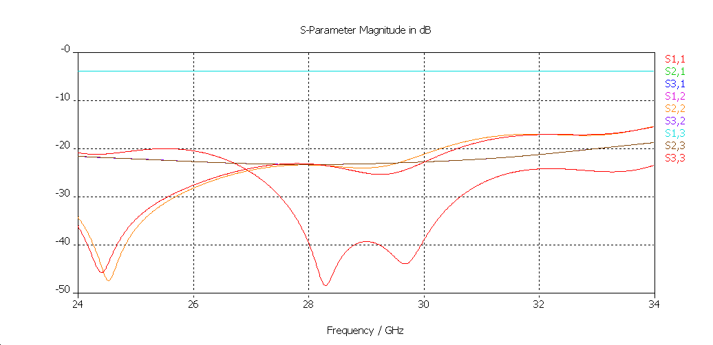
- PowerDividerAssembly_A.pdf: Power divider assembly, with 3db pads and alumina lines, S21 and S11, cover off
- PwrDividerOnlyCoverOff.pdf: Pwr divider only, cover off, no attenuator, no short alumina microstrip line.
- PwrDividerOnlyCoverOn.pdf: Pwr divider only, cover on, no attenuator, no short alumina microstrip line.
- PwrDividerS22.pdf: Pwr divider only, isolation plot
- MCLI PS8-54 (purchased) POWER DIVIDER TEST RESULTS:
- 8wayPowerDividerSpecSheet.pdf: MCLI PS8-54 datasheet
- 8wayPowerDividerTestData.pdf: MCLI PS8-54 power divider test data
Quartz Edge Coupled Filter (Bandpass)
- Below, Quartz filter test fixture shown with profiled top cover, 24.8 - 34.3 Ghz,
- Cavity dimensions, cover off: 0.44 wide x 1.54 long x 0.24 deep (inches)
- Photo by Bill Saxton :

- Below, Close-up of quartz filter test fixture, 24.8 - 34.3 Ghz, Photo by Bill Saxton:
- Cavity dimensions, cover off: 0.44 wide x 1.54 long x 0.24 deep (inches)
- Photo by Bill Saxton :

- QUARTZ FILTER MODELING RESULTS:
- The discrepancy between the CST model and MWO model is primarily the effect of the tapered quartz transition between the 50 Ohm line (25 mils) and the 9.4 mil alumina line. The MWO office model suggests a better S11 and S21 performance than measured. This model did not include the tapered transition with only the 50 Ohm line as input (Model M1). Once the taper is included(Model M2), the match tends to agree with the CST models and the measured results. Several various CST models were executed in an attempt to simulate the measured results. The quartz filter without the K connector beads in both a closed and open cavity, Models C1 and C2, respectively. The quartz filter in an open cavity with K connector beads, Model C3. The quartz filter without the alumina transitions, but with the quartz transitions with K connectors in a closed and open cavity, Model C4 and C5, respectively. And finally a CST model without the quartz and alumina transitions and without the vias in to compare the MWO models and CST models(C6,C7,C8).
- CONCLUSION
- The quartz CPW transitions did not provide adequate impedance match. The model C6-8 of the scribed and broken substrate indicate an improvement, although the wider bandwidth differs from the MWO model, M3.
- CST models predict better than -10 dB return loss with no CPW transition. Either a spark plug K connector transition (Matt Morgan's design) or a straight thru connection should work, although the straight thru is much more dependent upon machining. Both types were modeled giving similar results. Addition of the Corning glass 7070 bead with an air line coax between the bead and microstrip line degrade the return loss by 10 dB.
- 403arch_nobead.bmp: CST (TS) model of spark plug transition without glass bead.
- 403arch_bead.bmp: CST (TS) model of spark plug transition with glass bead.
- 403arch_bead_CPW_10Al.bmp: CST (TS) model of spark plug transition with glass bead, CPW transition, and 10 mil Alumina microstrip line.
-
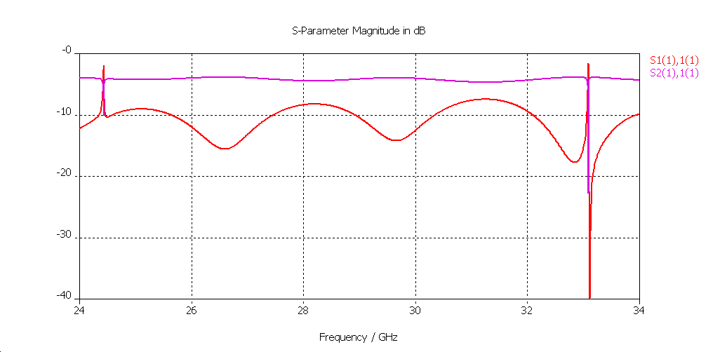
- More evidence to support poor match from transitions. Measured data from one section with narrow bandwidth design: Note the mismatch at 32 GHz and dip in S21 response.
-
-
- Quartz_noCPW_S21.pdf: Quartz filter with CPW transition removed.
- Quartz_short_S11.pdf: Measured S11 Quartz Filter with K connectors.
- Quartz_short_S21.pdf: Measured S21 Quartz Filter with K connectors.
- Quartz_short_CST.pdf: CS(TS)Model of Quartz Filter no alumina transition, no K connectors.
-
- CST MODEL
- Model C1 QuartzFil_K_V_closed.bmp: CST model(transient solver) with closed cavity, no K connectors, alumina transitions present
- Model C2 QuartzFil_nK_V.bmp: CST model(transient solver) with open cavity, no K connectors, alumina transitions present.
- Model C3 QuartzFil_K_V.bmp:CST model(transient solver) with open cavity, with K connectors, alumina transitions present.
- Model C4 QuartzFil.bmp: CST model(transient solver) with closed cavity, with K connectors, no alumina transitions.
- Model C5 QuartzFil_open.bmp: CST model(transient solver) with open cavity, with K connectors, no alumina transitions.
- Model C6 QU_freq_nK_nV_short_S11.bmp: CST model (TS) Scribe and shorten model. Eliminated quartz transition, 50 Ohm is 60 mils.
- Model C7 QU_freq_nK_nV_short_S21.bmp: CST model (TS) Scribe and shorten model. Eliminated quartz transition, 50 Ohm is 60 mils.
- Model C8 QU_freq_nK_nV_short_S21_MAG.bmp: CST model (TS) Scribe and shorten model. Eliminated quartz transition, 50 Ohm is 60 mils.
- Microwave Office MODEL
- Model M1: Cascade.pdf: Microwave Office Model updated April 13, 2010; no tapered transitions and no vias.
- Model M2: Quartz_Filter_MWO.pdf: Microwave Office Model updated April 13, 2010; with tapered quartz transitions and vias.
- Model M3: MWO_Shorten_Substrate.pdf: Microwave Office Model April 14, 2010; shortened 50 Ohm transmission line.
- Model M4: Filter_Response_w_CPW.pdf: Microwave Office Model April 15, 2010; Quartz Filter with transitions modeled as CPW.
- QUARTZ FILTER TEST RESULTS:
- QuartzFilter.pdf: Quartz filter in test fixture
- WgFilter.pdf: Ka-band waveguide high-pass filter for reference
_Lower LO (8.9 GHz) Documentation_
- 8900 Mhz LO amplifier test fixture, Photo by Bill Saxton
- Amplifier based on Hittite HMC451

- 8900 Mhz AMPLIFIER TEST RESULTS:
- 8900 Mhz amplifier.pdf: 8900 Mhz lower LO amplifier
Original schedule
- Quartz_short_S11.pdf: Quartz_short_S11.pdf
- Quartz_short_S21.pdf: Quartz_short_S21.pdf
- Quartz_short_CST.pdf: Quartz_short_CST.pdf
- 403arch_bead.bmp: 403arch_bead.bmp
- 403arch_nobead.bmp: 403arch_nobead.bmp
- 403arch_bead_CPW_10Al.bmp: 403arch_bead_CPW_10Al.bmp
- Wilk_split_FS_Kconn.bmp: Wilk_split_FS_Kconn.bmp


Edit | Attach | Print version | History: r37 < r36 < r35 < r34 | Backlinks | View wiki text | Edit wiki text | More topic actions
Topic revision: r37 - 2010-07-21, StevenWhite


- Webs
-
 ALMA
ALMA
- NAASC
- SCIIPT
- CDL
- CICADA
- Ccs
- Littlethings
- Cville
- DSAA
- EVLA
- FASR
- GB
- Computing
- Data
- Dynamic
- Electronics
- Gbtpipeline
- Knowledge
- Mechanical
- Observing
- WbandVLBACal
- Obsreports
- Operate
- PTCS
- OOF
- ServoImprovementsHome
- ServoSiteAcceptTestProcs
- Pennarray
- Projects
- Recreation
- Scicenter
- Skynet
- Software
- CLEO
- StaffEvents
- TACTool
- HPC
- JVLA
- KPAF
- Library
- Main
- Metrics
- NGVLA
- NM
- Computing
- Electronics
- OSAA
- OSX
- SRDP
- Software
- Algorithms
- CASA
- Splat
- System
- VLBA
Ideas, requests, problems regarding NRAO Public Wiki? Send feedback