|
|
You are here: NRAO Public Wiki>EVLA Web>EVLACommissioning>EVLACommissioningOrganization>PhasedArray (2011-09-28, MichaelRupen)
Edit wiki text
Edit
Attach
Print version
Phased Array
- Phased Array
- Scope
- Group
- Coarse Commissioning Plan and Status
- Background
- Outstanding Issues
- Testing Logs
Scope
The EVLA will be used in phased array modes for two main types of science: VLBI, and time domain studies of pulsars and transients. This group will develop and execute the tests required to bring this observing mode into operation and make it available to the community.Group
- RSRO: Adam Deller, Joseph Lazio
- NRAO: Walter Brisken, Amy Mioduszewski, Jon Romney, Michael Rupen, Ken Sowinski
Coarse Commissioning Plan and Status
| ECSV task | ECSV subtask | Target | Responsible | Quarter | Status |
|---|---|---|---|---|---|
| ECSV-89 | - | Phased array EVLA documentation | Mioduszewski | 2011Q2 | |
| - | ECSV-44 | Phased EVLA verification tests documentation | Deller | 2010Q2 | |
| - | ECSV-88 | Phased array observer recommendation documentation | Lazio | 2011Q2 | |
| ECSV-90 | - | Phased array observing mode support | Deller | 2010Q4 | |
| - | ECSV-93 | OPT support for phased array | Butler | 2011Q1 | |
| - | ECSV-91 | Switched power detection | Rupen | 2010Q4 | |
| - | ECSV-92 | executor operation of phased array | Rupen | 2010Q4 | |
| - | ECSV-94 | vex2script generation of .evla/.vci files | Deller | 2010Q4 | |
| ECSV-95 | - | Phased EVLA non-VLBI verification (Parent) | Deller | 2010Q4 | |
| - | ECSV-96 | On-chip tests of the RXP phase rotation | Deller | 2010Q2 | |
| - | ECSV-97 | Bright pulsar/spectral line test | Deller | 2010Q2 | |
| - | ECSV-98 | 4-bit/8-bit mode test | Lazio | 2010Q2 | |
| ECSV-99 | - | Single phased array VLBI (Parent) | Deller | 2011Q2 | |
| - | ECSV-100 | Single phased output | Deller | 2010Q4 | |
| - | ECSV-101 | Transfer of phased beam across the sky | Brisken | 2011Q1 | |
| ECSV-102 | - | Phased array deployment (Parent) | McMullin | 2011Q2 | |
| - | ECSV-103 | e2e test through OPT | Mioduszewski | 2011Q2 | |
| - | ECSV-104 | Initial phased subarrays (Y1, Y27) | Mioduszewski | 2011Q2 | |
Background
Much of the discussion is based on an EVLA memorandum (in prep.) by A. Deller. For reference, Figure 1 from that memo is reproduced here. Another important reference is the baseline board Re-timing, X-bar, and Phasing (RXP) FPGA, available from the https://mitr.drao.nrc.ca/widar/private/Baseline_Board.html WIDAR documents site.
Outstanding Issues
[List taken from discussion at the June 17 "Thursday" correlator discussion, AD's memo, and AD emails.] * How do phasing solutions carry across to adjacent subbands? (Produce new vci document for the existing 16 MHz W3OH or continuum C-band tests, with two subbands) * A VLBI test to PT or LA, which would require home-brewed scripts (completed) * Bringing vex2script and the OPT up to scratch in the .evla and .vci files they write (using the existing script/vci document as a template) * Starting to look at the WIDAR output and trying to generate some estimation of Ta/Tsys (casa script)Testing Logs
2011 Sept 26
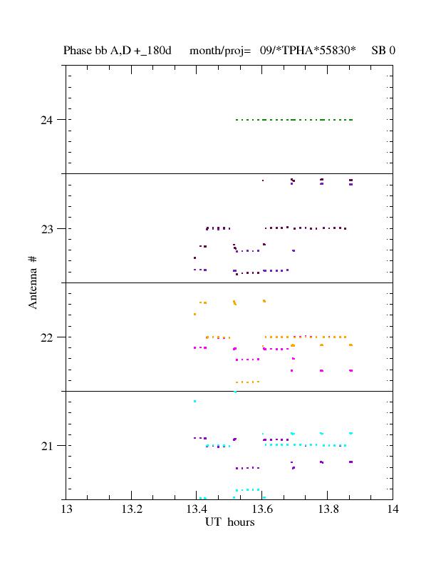
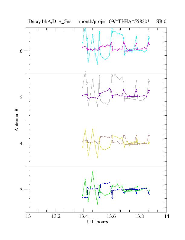
Purpose of Test: Testing if user could phase up in 3 scans only and, then apply for 5 minutes and then reset the delays (i.e. turn off apply delay and phase) and phase up again. A "block" is 1x10sec determine autophase + 2x10sec determine autophase+apply delay and phase + 5x1min apply delay and phase. Result: The first block phased fine, second block went off to another phase, third block phased for subband D but not A, 4 and 5th blocks were fine, see figure 1 (scale is +-180 degrees; number on the left is antenna number). Some of this can be explained by reference antenna oddness, antenna 24 (which is the default reference antenna) was not present until after the first block, when antenna 24 is not there telcal uses ante 1, 2, etc until it finds an antenna present. Ante 1 was not there so it should have chosen ante 2, which was present. So for the first block ante 2 should have been the reference, and it phased up fine (although there is the oddity that if ante 2 was the reference antenna its phases should have been 0, but they are not). Then ante 24 appears 2 scans into the second block, so the first two autophase scans were missed by ante 24 so it does not have enough scans to phase up, but since it is the reference ante block two does not phase up. But there is no explanation why subband A does not phase but subband D does for block 3. The delays for subband A behave very strangely (swinging wildly by several ns, see figure 2 (scale is +-5ns; number on the left is antenna number)) at first but seem to settle down by the second block. Problems that need to be fixed: Switching reference antennas mid-observation is a very bad idea in most cases, can this be fixed so that telcal sticks to one reference antenna unless explicitly told to switch? Also there was supposed to be a tool that allowed the operator to select a reference antenna, is that implementable?2011 Sept 17
Purpose of test: Testing if user could phase up in 3 scans only and if applying the delay continuously would work even better than test on Sept 8. So every 5 minutes there would be a 3x10sec autophase loop but the delay and phase was applied continuously, except for the first autphase loop. For the first autophase loop the first scan is autophase only, and then 3x10scans autophasing and applying. Result: In this test it looks the first autophase loop is the only one that does anything, after 2 autophase scans the baselines are phased up. Unfortunately, for this test, most of the baselines are rock steady at 0 phase for the entire half hour after the first autophase loop. But antenna 1 doesn't get to source until after the first phasing loop and it never phases up; and a few baselines wander away from 0 as much as 90 degrees and are never fixed. After discussion with Barry, it turns out that "the phasing objects are created, but then are never used for anything, so the old phasing objects created in scan 3 continue to be used, and, since they are disconnected, they never change." Therefore for the autophase to be applied they need to be reset at the beginning of the autophse loop. It is still unclear if this can be fixed in the OPT or it will require more work. At minimum if this is not a viable way to schedule, then it should be prevented.2011 Sept 8
Purpose of test: To test Barry's fixes. Default is now a delay-only autophase. Scheduled 10 autophase scans and applying phase and delay to all but the first (i.e., first autophase scan did not apply phase and delay, effectively resetting the phase for each block) then apply-only for a few minutes. There were several blocks using 5, 8, 10 and 15 second scans. Result: Test worked great, the array seemed to phase up in 3 scans, no matter what the scan length. If you look at the delays there seems to be an adjustment after 3 scans and then another small adjustment after 3 more, but the phases look great after the first adjustment. There were two other test that day which failed because tester error.2011 July 7
Purpose of test: To see if we could autophase with one scan and then apply to scans thereafter. Result: Didn't work at all, phases pretty much remained random. Called Ken and it was his belief that we needed at least 2 minutes autophasing before application, old description by Barry implied that at least 5 scans are needed to phase up. Both of these were tested and it seemed that once autophasing was turned off and phase were just applied, it took 30-60 seconds for that to make the phases close to zero. However we had several scans in the apply phase block and it looked like something was being applied, but phases didn't go to zero. Ken did further testing later in the day and here are his comments: I setup a file using 3C273 to: 1. Spend two minutes with short scans to phase the array 2. disconnectPhasing() so that further telcal solutions are ignore 3. Alternate 30 second scans with and without phase solutions applied. and learned: It takes 8 to 10 scans to phase the array. Delays have been zeroed by the fourth scan and it takes another five or so scans to zero the phases. I tried this with both 10 and 8 second scans. If disconnectPhasing() is not done and the targets are marked as a calibrator the behavior is not very robust. With disconnectPhasing(), I see exactly the expected behavior: scans alternate between zero delays and phase, and the initial delay and phase. Amy's comment on Ken's test and conclusion: This means that our test earlier in the day did not phase up because calibrate complex gain was checked in the intents for all the scans. This was done because it must be done in order to see the phases in telcal. However I am still confused because we did see phasing up just really late phasing up, also in previous test it seemed to take 4-5 subscans to phase up not 8 or 9.2011 June 17
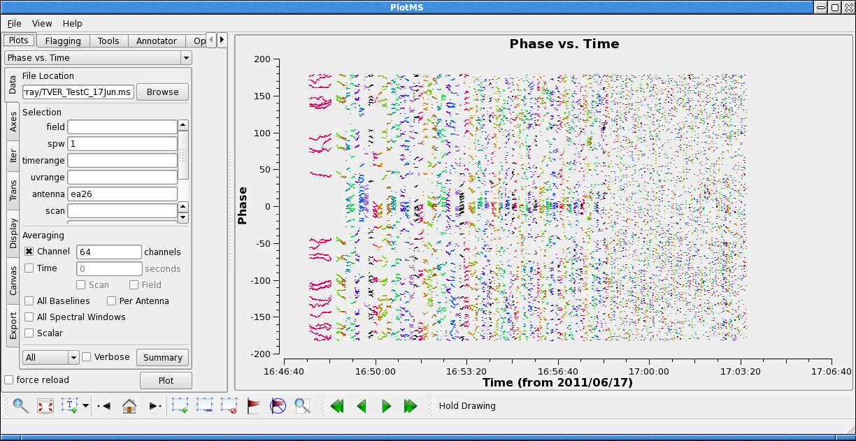
Follow-up on some of Amy's proposed observations; three separate tests:- Repeat Amy's tests (phasing with cycles of 10x(3xJ0217+7349 for 10s), 20x(3xJ0217+7349 for 5s) and 50x(3xJ0217+7349 for 2s) each). For Test A, we had a long slew source scan and a short 10s scan initially with no phasing.
- SB: TVER0001_sb4308784
- Test B: As above but toggling Determine autophase on and off (i.e., middle scan of the 3 had this off); for Test B, we had a 70s slew scan and a short 10s scan initially with no phasing.
- SB: TVER0001_sb4505976
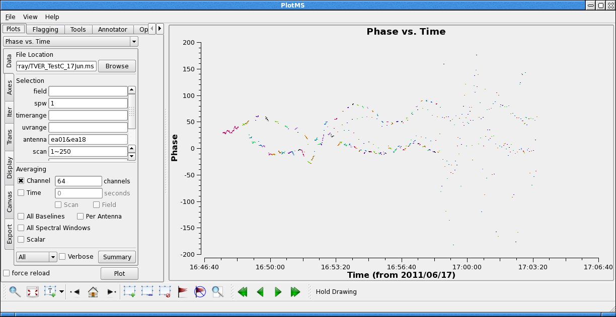
- Test C: As above but toggling apply last autophase on and off (i.e., middle scan of the 3 had this off); for Test C, we had a 70s slew scan and a short 10s scan initially with no phasing.
- SB: TVER0001_sb5452708
- Test A

- Test B

- Test C

- Test C - Good baseline

- Test C - Bad baseline

2011 May 30
Ken - responding to Amy; following morning tests. 1) Ran Adam Deller's last test and it phased up fine after ~1 minute of phasing. My schedule (SB4213195) did not. This was traced to the fact that SB4213195 was using sbid 1, rather then sbid 0. SB4213195 instrument configuration does have an "subband configuration" SPB1. When sbid 0 was forced then phasing worked fine. I look at this more carefully this morning and find evidence of a problem in the executor or telcal. Phases measured in subband 1 are not noticed when the executor tries to correct the phase. I suspect, but have not yet examined the code, that it works only for subband 0. I will look into these in the next week. 2) We were evidently not able to communicate with mark5c unit. That was because the MIB "emulation" software was not running. Walter has fixed that and arranged so that it will startup whenever the machine is booted in the future. 3) I examined the data in AIPS which confirmed the phasing. There were three segments to the SB, 32x10 second scans, 30x5 second scans, then 9x20 second scans. Some interesting features (All comments based on IF2, stokes LL, baselines to antenna 26, which I think was hardwired as the reference. IF1/RR shows similar.): -all but 5 of the antennas (26 in total) phased up in first set of- second scans and remained phased throughout. -it took 6-7 scans (60-70 seconds) to phase up during the 10 second block -antenna 2 phases lost coherence on scan 14 of the 5 second block and never recovered.
2011 May 27
Hi Joe and Ken, I wanted to write something up so I remember what happened in 3 weeks and know what I want to do next. Feel free to add anything I forgot. Present: Ken Sowinski, Joe McMullin, Amy Mioduszewski 0) Discovered that the for SBs that use array phasing, scan/loops cannot be moved or deleted. Reported and OPT should be fixed next week. 1) Ran Adam Deller's last test and it phased up fine after ~1 minute of phasing. My schedule (SB4213195) did not. This was traced to the fact that SB4213195 was using sbid 1, rather then sbid 0. SB4213195 instrument configuration does have an "subband configuration" SPB1. When sbid 0 was forced then phasing worked fine. 2) We were evidently not able to communicate with mark5c unit. 3) I examined the data in AIPS which confirmed the phasing. There were three segments to the SB, 32x10 second scans, 30x5 second scans, then 9x20 second scans. Some interesting features (All comments based on IF2, stokes LL, baselines to antenna 26, which I think was hardwired as the reference. IF1/RR shows similar.):- all but 5 of the antennas (26 in total) phased up in first set of 10 second scans and remained phased throughout.
- it took 6-7 scans (60-70 seconds) to phase up during the 10 second block
- antenna 2 phases lost coherence on scan 14 of the 5 second block and never recovered.
- antennas 12, 14 and 22 phases all jumped away from 0 by 50-80 degrees then take up to 8-10 5 sec scans (40-50 sec) to get back to phased. This occurs on scans 19, 22 and 20, respectively, in the 5 second block.
- antenna 15 over 1.5 10 second scans drifts from 0 to 180 and back.
2011 February 18
This covers the time range from Jan 10 to Feb 18. Apart from a couple of early tests using the "old" approach of production system + baseline board GUIs, all tests were conducted using by running the test executor from the command line. The following subsystems were tested independently and then concatenated: 1) The OPT/RCT + model2script, to ensure the production of valid executor scripts and VCI files- The 3.08 version of the webtest OPT and test model2script were used. These will be brought into production shortly
- Note: If the executor is linked against an out of date VCI schema, it will silently ignore the parts of the VCI file that it doesn't understand
- The 15Feb snapshot of CM was used. This will be brought into production shortly
- The first was that the executor (whose Mark5 module was essentially generalised from the VLBA executor code) currently takes the commanded Mark5 record start time and moves it forward in time by 2 or 3 seconds. However, the time of the configuration of the recorder (including the scan name) by default takes place at the scan boundary - so if recording is commanded to start exactly on a scan boundary (our initial default) it will actually begin several seconds early, and the record scan not will not yet be set, leading to no recording taking place. This feature was not documented, and whilst it makes sense in VLBA observe scripts it is undesirable from an EVLA viewpoint. A temporary fix has been instituted to delay the recording command to 5 seconds after a scan start, but a more elegant fix which avoids potential lost on-source time is planned.
- A second issue worth noting is that the drs program must be killed to inspect the contents of the Mark5 module, since it retains a lock on the communications path that an inspection requires. This is a testing-specific issue, since under normal circumstances the disk modules will not be inspected on-site (they will be shipped back to Socorro for correlation). However, when testing, it is often desirable to export data from the module. However, when drs is killed to allow this to happen, the MIB emulator program times out and does not reconnect when drs is restarted, although in theory it should. Thus, every time drs is killed/restarted, the MIB emulator should be too.
- 1x128 MHz subband (1 x single pol)
- 2x128 MHz subband (1 x dual pol)
- 2x64 MHz subband (1 x dual pol)
- 4x64 MHz subband (2 x dual pol)
- 8x16 MHz subband (4 x dual pol)
| Bandwidth | Number of bands | Total data rate | Min packet delays (microsec) | Packet loss % |
| 128 | 1 | 512 Mbps | 5 | 0 |
| 128 | 2 | 1024 Mbps | 0,0 | 43,0 |
| 128 | 2 | 1024 Mbps | 5,5 | 43,0 |
| 128 | 2 | 1024 Mbps | 10,10 | 41,0 |
| 128 | 2 | 1024 Mbps | 7,11 | 0.06,0.06 |
| 64 | 2 | 512 Mbps | 5,5 | 41,0 |
| 64 | 4 | 1024 Mbps | 5,5,5,5 | 100,100,0.2,0.1 |
| 16 | 8 | 512 Mbps | 5,5,5,5,5,5,5,5 | 41,56,50,83,48,43,37,41 |
 DiFX testing
Due to the nature of current VLBI formats with samples multiplexed together into a single stream, the DiFX software correlator does not process subbands independently. In multiple thread VDIF data, the separate subbands are packetized separately, so some reframing of the data is necessary in order for DiFX to efficiently process it. DiFX can actually handle multiple separate datastreams for a single antenna, but conveying this information through the correlator setup program (vex2difx) would be rather complicated and is not supported at this time. (vex2difx currently has an explicit assumption of just one datastream per antenna). In addition, with a single Mark5C recorder the packet streams are not written to separate files anyway, but the packets are interlaced into a single file - which DiFX does not currently support. Thus, some reframing is necessary.
The easiest path towards DiFX support of multithread VDIF data is to reframe the data with multiplexed samples into a single packet stream (so more like traditional VLBI formats). This is a relatively simple corner turn - a bunch of packets are read into memory, appropriately aligned, and then samples drawn from each of the N source thread packets and reframed into a single output packet which is N times larger. The existing VDIF infrastructure in DiFX is already set up to decode such multiple subband data when multiplexed in this fashion, and so only the buffering and corner turning needs to be implemented.
In early January, an offline path for this data reframing was established and tested. After data has been exported from the Mark5 module, a two stage file conversion was performed. The first (cleanVDIF) passes through the file and strips out any non-VDIF packets which the Mark5 has mistakenly recorded (a "feature" which will go away once recording filtering based on packet length is enabled "soon"). The second (multi2singlethreadVDIF) buffers a number of packets, orders them by thread and time, and multiplexes the data into a single VDIF thread and writes it back out. This was tested with twin 16 MHz bands on the W3OH maser (shown in the Jan 10 test log below).
Avoiding the next for offline data translation steps requires that buffering / bad packet rejection / deinterlacing / multiplexing to be ported inside DiFX. This has already been accomplished for file-based correlation, and tested by correlating a raw exported file against a file already translated offline by multi2singlethreadVDIF. Adding this functionality to module-based correlation (the normal mode of operations for the VLBA, avoiding the need for a file exporting) should be relatively simple, as the code is simple and modular, and should just require some copying and pasting, then testing.
Configuring the DiFX correlator to read multiple thread VDIF data requires a single format string to be added to the ".v2d" correlator setup file. This format string requires the VDIF packet length, the number of threads, and the thread IDs. The allocation of threadIDs to subbands is controlled by Configuration Mapper following an algorithm determined by basebandID and subbandID. The string format follows "INTERLACEDVDIF/0,1,868,869/1032/2" where in this example 0,1,896,897 are the threadIDs for the four threads, 1032 is the packet length, and 2 is the number of bits. The order of these threadIDs should match the order of the subbands in the vex file for VLBI observations.
DiFX testing
Due to the nature of current VLBI formats with samples multiplexed together into a single stream, the DiFX software correlator does not process subbands independently. In multiple thread VDIF data, the separate subbands are packetized separately, so some reframing of the data is necessary in order for DiFX to efficiently process it. DiFX can actually handle multiple separate datastreams for a single antenna, but conveying this information through the correlator setup program (vex2difx) would be rather complicated and is not supported at this time. (vex2difx currently has an explicit assumption of just one datastream per antenna). In addition, with a single Mark5C recorder the packet streams are not written to separate files anyway, but the packets are interlaced into a single file - which DiFX does not currently support. Thus, some reframing is necessary.
The easiest path towards DiFX support of multithread VDIF data is to reframe the data with multiplexed samples into a single packet stream (so more like traditional VLBI formats). This is a relatively simple corner turn - a bunch of packets are read into memory, appropriately aligned, and then samples drawn from each of the N source thread packets and reframed into a single output packet which is N times larger. The existing VDIF infrastructure in DiFX is already set up to decode such multiple subband data when multiplexed in this fashion, and so only the buffering and corner turning needs to be implemented.
In early January, an offline path for this data reframing was established and tested. After data has been exported from the Mark5 module, a two stage file conversion was performed. The first (cleanVDIF) passes through the file and strips out any non-VDIF packets which the Mark5 has mistakenly recorded (a "feature" which will go away once recording filtering based on packet length is enabled "soon"). The second (multi2singlethreadVDIF) buffers a number of packets, orders them by thread and time, and multiplexes the data into a single VDIF thread and writes it back out. This was tested with twin 16 MHz bands on the W3OH maser (shown in the Jan 10 test log below).
Avoiding the next for offline data translation steps requires that buffering / bad packet rejection / deinterlacing / multiplexing to be ported inside DiFX. This has already been accomplished for file-based correlation, and tested by correlating a raw exported file against a file already translated offline by multi2singlethreadVDIF. Adding this functionality to module-based correlation (the normal mode of operations for the VLBA, avoiding the need for a file exporting) should be relatively simple, as the code is simple and modular, and should just require some copying and pasting, then testing.
Configuring the DiFX correlator to read multiple thread VDIF data requires a single format string to be added to the ".v2d" correlator setup file. This format string requires the VDIF packet length, the number of threads, and the thread IDs. The allocation of threadIDs to subbands is controlled by Configuration Mapper following an algorithm determined by basebandID and subbandID. The string format follows "INTERLACEDVDIF/0,1,868,869/1032/2" where in this example 0,1,896,897 are the threadIDs for the four threads, 1032 is the packet length, and 2 is the number of bits. The order of these threadIDs should match the order of the subbands in the vex file for VLBI observations.
2011 January 20
Successful test of the phased array + Mark5C recorder, duplicating the earlier (October, June) tests which showed expected increase in S/N. This test was again 16 MHz bandwidth on W3OH. For the first time, two subbands (both polarisations of the same bandwidth) were simultaneously recorded, and the resulting interleaved packet stream was exported from the Mark5C, deinterlaced and spectra produced from both polarisations. No packet loss was seen. The resultant spectra are shown here:
Notes on setup, for posterity:
Schedules etc
The VCI documents and executor scripts reside in: /home/mchost/evla/scripts/test/phasing/19Jan2011/Baseline board GUI Setup
Do once per baseline board you want to use:- Set up the RXP with the following:
- Enable phasing: on
- Enable VDIF: on
- Set requantiser ALC checkbox on
- Station ID: EE
- Thread: 0 (or 1 for second board)
- Frame size: 250 [Remember this is in units of 4byte words, so it is setting 1000 byte frames]
- Epoch: 0
- Offset(s): 127057024
- Make sure invalid bit is not set!!
- Set baseband Id, looking at the column in the RXP section to figure out whether baseband 0/1 means 0, 2, 4, or 6 [= A, C, B, D]
- Destination Mac address:12:34:56:78:90:00
- Destination IP address: 192.168.0.21
- Src and Destination port:
- VDIF Packets: on SFP2
- Priority: VDIF
- Set interframe delays to 5 us
Running the Mark5C recorder manually
The mark5 machine may change, and if so the presence of software etc should be double checked before observing starts. Also check that there is a disk module present and the Mark5 has the requisite key to turn it on!- Make sure that MARK5_DIR_PATH is set to something that exists!
- log in and set up the difx tools with ". setup_difx"
- run drs
- in a separate window, log in and run drs_client
- In drs client, run the following to start, inspect and then stop recording:
-
packet=32:0:1032:0:0; # offset:??:packet length:??:??
-
record=on:<filename>;
-
record?; # Inspect what's happening
-
record=off;
-
- Kill both drs_client and drs, so you can access the module (A below assumes it is in bank A - use "B" instead of "A" if necessary:
-
mk5dir -v A (read directory)
-
mk5cp -f -v A <scan number> .
-
printVDIF <exported filename> <Mbps/thread>
-
- Before further analysis, you may want to clean the file (if the issue of periodic short ARP packets from the switch, which are recorded by the Mark5C, is not yet resolved), and deinterlace/multiplex it if there was more than one thread:
-
cleanVDIF <VDIF input file> <VDIF output file> <Mbps/thread>
-
multi2singlethreadVDIF <multithread VDIF input file> <multiplexed singlethread VDIF outtput file> <Nthreads> <Mbps/thread> <threadId0> <theadId1> ... [threadIdN-1]
-
- Then you can inspect autocorrelation spectra if you want:
-
m5spec <VDIF file> VDIF_<packet bytes exc. header>-<total Mbps>-<Nthreads>-<Nbits> <Nchannels> <NFFTs> <output filename>
- examples of common VDIF format strings are VDIF_1000-64-1-2 (one 16 MHz band), VDIF_2000-128-2-2 (two 16 MHz bands after multi2singlethreadVDIF)
-
2010 June 25
Discussion with Sonja V., Michael R., Barry C., Ken S., and David H. about changes to the VCI document to enable phased array support. Consensus was to have the VCI element phasedArray have 3 children, 1 related to the setup of the RXP chip and 2 related to the output formats, looking something likephasedArray -
phaRXPSetup -
phaDatToCorrChipArray -
phaDatatoVDIF
phasedArray element itself would be a child of subBand.
For reference, the previous (and quite dated) description of the phased array-relevant portions of the VCI document can be obtained from the WIDAR VCI site (elements pha*).
2010 June 23
At the "Wednesday correlator meeting," Brent C. reports that his initial hypothesis about the cause of the DC bias in the phasing output was not correct. He is exploring another one.2010 June 22
Barry C. changed the format of autophasing within the Executor. > A change in formulation of autophasing. The recommended form for invoking autophasing is now:>
> phs = subarray.registerPhasing(String subbandName)
> to connect the object phs to the phase listener,
> and
> subarray.usePhasing(phs)
> connect the object phs to the phase and delay calculations.
>
> X band still doesn't phase - the simple fix I had in mind didn't work.
2010 June 18
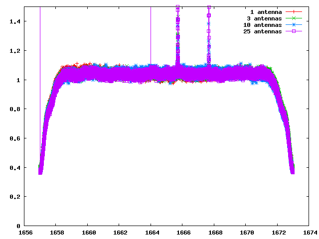
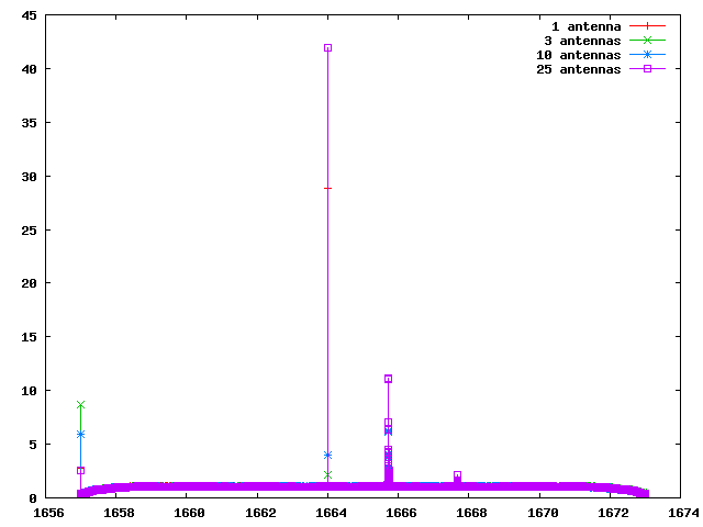
Adam D. and Michael R. (with Joe L. present at the start) re-ran the 16 MHz band phasing test on W3(OH). This figure image shows the increase in SNR as more antennas are added. The improvement is not quite the expected linear increase. However, at one stage an antenna with no L band receiver was included, and it is not clear that phasing was maintained over the entire duration of the test. The image itself is made by autocorrelating the VDIF output frames, from about a few 100 ms of data. During the test, AD also produced the spectrum of the entire 16 MHz band. There is a big birdie at 1664 MHz, but overall this 16 MHz band is fairly clean. It is also possible to see the 1667 MHz maser line.
 Finally, in previous tests, the bandpass shape has been poor, showing many ripples. The current bandpass appears quite flat, a considerable improvement, presumably because of one of the FPGA code updates made.
2010 June 10
Brent C., Michael R., Ken S., and Joe L. performed a series of tests on an RXP chip. The goal was to compare the phase residuals from normal cross-correlation with phase residuals produced by cross-correlation via the phased data path. If successful, the interferometer-determined phase residuals, when applied to zero residual delay and phase, will result in perfect phased-array coherence. These tests represent (a portion of) the tests in Section 6.5.1 of the Deller et al. EVLA memorandum. All tests were performed on baseline board B101-t3 using only the baseline ea01-ea28 (pads W09 and N09, respectively). Signals from these antennas were routed for normal cross-correlation through X0Y0 and via the phased data path through X3Y7. The differential phase shift was 540 kHz (27 * 20 kHz per antenna). Test 1: X-band observation of 3C 84, with OSRO1 mode (128 MHz). A quick look observation at the time of the test comparing the two signal paths showed "good" agreement to the eye. The test was repeated at 64 MHz bandwidth and the results were similar. Subsequent analysis by BC showed no statistical differences between the two signal paths for either bandwidth. Test 2: L-band observations of the OH maser in W3(OH). The bandwidth was 16 MHz. The first test was a 5-second integration, and there was "good" agreement between the two signal paths. The test was repeated with an 80-second integration. Subsequent analysis by BC showed no statistical differences between the two signal paths. However, one of the goals of this test is ultimately to confirm that the phased-array block is handling the phase correctly. The phased-array block implements phasing by a 9-bit representation of sine and cosine, which should limit the phased-array output to 54 dB. The 80-s integration was not long enough to reach this dynamic range. A DC bias was detected in the phased cross-correlation, subsequently found to be in the phased 4-bit requantizer. As of the correlator meeting of 2010 June 16, BC believes that he has identified the problem and a fix. This document provides more details on the normal vs. phased cross-correlation, courtesy of BC. It demonstrates the phase agreement between the two signal paths for the 128 MHz continuum test.2010 June 3
Ken S. and Joe L. performed a series of phasing tests on the executor-TelCal portion of the system. The tests were at C band, RCP. The tests involved phasing on 3C 84, attempting to transfer the phasing to J0359+5057/B0355+508, then reversing the process. (Note that B0355+508 is the source that Adam D. had been using in many of his phasing tests.) This figure shows the antenna phases for the phasing scans on 3C 84 (a.k.a. VA mode in the VLA system). The phases are random in the first scan, consistent with the solutions still being derived, but then settle down. An estimate by eye suggests an rms phase of order 0.1 radians. These data are at the native time resolution (1 second) and are color-coded by antenna. This figure shows the antenna phases for the application scans on B0355+508 (a.k.a. VX mode). These data are at the native time resolution (1 second) and are color-coded by antenna; note the change in scale. A similar rms phase estimate appears to hold.
 This figure shows the antenna phases for the phasing scans on B0355+508. The phases are random in the first two scans scan, consistent with the solutions still being derived, but then settle down. An estimate by eye suggests an rms phase of order 0.1 radians. These data are at the native time resolution (1 second) and are color-coded by baseline. It is not obvious why the phases become random on the first two scans, perhaps other than that by telling the executor to re-register the phases, it requires a scan for the phases to settle down again.
 This figure shows the antenna phases for the application scans on 3C 84. These data are at the native time resolution (1 second) and are color-coded by baseline; note the change in scale. A similar rms phase estimate appears to hold.
 We conclude that phase transfer is working correctly, at least as far as the executor and TelCal are concerned.
(ca.) 2010 May 19
Ken S., with contributions from Joe L., has performed a series of tests on the executor-TelCal portion of the phasing. All of the tests have been using the source 3C 84 and for RCP. Phasing LCP does not work.| Bandwidth | ||||
| Band | Pol'n | 16 MHz | 64 MHz | 128 MHz |
| L | RCP | demonstrated | demonstrated | |
| [S] | RCP | |||
| C | RCP | demonstrated | demonstrated | demonstrated |
| X | RCP | fail | ||
| [U] | RCP | |||
| K | RCP | demonstrated | ||
early 2010
Phasing tests by Adam D. Status not known.-- JosephMcMullin - 07 Jun 2010


| I | Attachment | Action | Size | Date | Who | Comment |
|---|---|---|---|---|---|---|
| |
Comparison_cc_vs_pcc_128cont_Jun10-10.pdf | manage | 56 K | 2010-06-16 - 13:29 | UnknownUser | comparison of normal cross-correlation with phased cross-correlation, from Brent C. |
| |
EVLA-2subband-W3OH.png | manage | 5 K | 2011-01-21 - 17:19 | AdamDeller | Image showing phased EVLA autocorrelation on W3OH, dual polarisation |
| |
EVLA-PSRJ1939_coherentdedisp.png | manage | 51 K | 2011-02-20 - 11:58 | AdamDeller | dedispersed pulse profile of PSRJ1930 from a single 128 MHz band |
| |
EVLA-phasing.jpg | manage | 53 K | 2010-06-14 - 16:10 | UnknownUser | diagram of EVLA phasing |
| |
Joe_17Jun_IF1_LL_EA26.png | manage | 86 K | 2011-06-20 - 20:11 | JosephMcMullin | |
| |
Joe_17Jun_IF1_LL_EA26_autophase.png | manage | 81 K | 2011-06-20 - 20:12 | JosephMcMullin | |
| |
Joe_17Jun_IF1_LL_EA26_uselast.png | manage | 120 K | 2011-06-20 - 20:12 | JosephMcMullin | |
| |
TVLB0002_20100603_3C84-VA.jpg | manage | 152 K | 2010-06-14 - 16:00 | UnknownUser | phases, 3C84, VA mode |
| |
TVLB0002_20100603_3C84-VX.jpg | manage | 241 K | 2010-06-14 - 16:02 | UnknownUser | phases, 3C84, VX mode |
| |
TVLB0002_20100603_B0355508-VA.jpg | manage | 141 K | 2010-06-14 - 16:02 | UnknownUser | phases, B0355+508, VA mode |
| |
TVLB0002_20100603_B0355508-VX.jpg | manage | 220 K | 2010-06-14 - 16:01 | UnknownUser | phases, B0355+508, VX mode |
| |
TestC_17Jun_BadBaseline.png | manage | 72 K | 2011-06-20 - 20:15 | JosephMcMullin | |
| |
TestC_17Jun_GoodBaseline.png | manage | 71 K | 2011-06-20 - 20:15 | JosephMcMullin | |
| |
w30h.bandpass.png | manage | 6 K | 2010-06-19 - 09:36 | UnknownUser | phasing test, bandpass of 16 MHz observations |
| |
w30h.phasingtest.png | manage | 6 K | 2010-06-19 - 09:34 | UnknownUser | phasing test of linearity on W3(OH) |
| |
w30h.wholeband.png | manage | 3 K | 2010-06-19 - 09:35 | UnknownUser | phasing test, entire 16 MHz bandwidth during W3(OH) observations |
Edit | Attach | Print version | History: r22 < r21 < r20 < r19 | Backlinks | View wiki text | Edit wiki text | More topic actions
Topic revision: r22 - 2011-09-28, MichaelRupen


- Webs
-
 ALMA
ALMA
- NAASC
- SCIIPT
- CDL
- CICADA
- Ccs
- Littlethings
- Cville
- DSAA
- EVLA
- FASR
- GB
- Computing
- Data
- Dynamic
- Electronics
- Gbtpipeline
- Knowledge
- Mechanical
- Observing
- WbandVLBACal
- Obsreports
- Operate
- PTCS
- OOF
- ServoImprovementsHome
- ServoSiteAcceptTestProcs
- Pennarray
- Projects
- Recreation
- Scicenter
- Skynet
- Software
- CLEO
- StaffEvents
- TACTool
- HPC
- JVLA
- KPAF
- Library
- Main
- Metrics
- NGVLA
- NM
- Computing
- Electronics
- OSAA
- OSX
- SRDP
- Software
- Algorithms
- CASA
- Splat
- System
- VLBA
Ideas, requests, problems regarding NRAO Public Wiki? Send feedback