|
|
You are here: NRAO Public Wiki>CICADA Web>GreenBankSpectrometer>AnalogIFInterface (2012-06-04, GalenWatts)
Edit wiki text
Edit
Attach
Print version
VEGAS: VErsatile GBT Astronomical Spectrometer
Analog IF Interface
(Scroll down for older information)
Gain Slope Modifications, June 2012
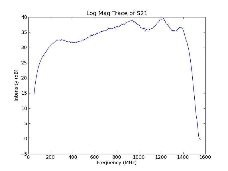
It is desired to modify the gain slope to compensate for the negative slope caused by various components and cables in the RF path. The long cables connecting the GBT Converter Modules to the VEGAS IF Modules were measured and contribute approximately 3.3 dB of negative gain slope across the 100-1400 MHz range. Initially the VEGAS IF Modules have a slope close to zero over the pass band,- VEGAS IF Module, before modifications:

- VEGAS IF Module, optimized after modifications:

Previous Postings:
Description
The Analog IF Interface conditions the signals from the GBT IF System to make them suitable for use by the new spectrometer. Level adjustment and anti-aliasing filtering are the primary functions, and the interface also provides test features such as test tone injection capability, input signal monitoring and a built-in noise source correlated for each pair of channels. An initial version of the specification is at http://www.gb.nrao.edu/gbsapp/report/analog.pdfBlock Diagram
- IFblockMultiFilter5.pdf: IF Interface Block Diagram, November 21, 2011
Control
Control of filter selection, test signal routing, etc. is detailed in IFControlBits.Anti-Aliasing Filters
The GBT IF system that precedes the Analog IF Interface for the spectrometer has a high pass characteristic that combined with capacitive decoupling that will be used in the gain section of the to-be-built analog interface a low pass filter should be sufficient for anti-aliasing. A low pass filter also simplifies fabrication (=lower cost) and would reduce pass band ripple since a band pass filter for the bandwidth we want will end up being cascaded high pass and low pass filters. For proper anti-aliasing the response of the filter should be at least 20 dB below the -3 dB cutoff at the high end of the sampling bandwidth ( S21 <= -20 dBc @ 1500 MHz). Additionally, we want to maximize the sampled bandwidth by having the -3 dB cutoff as close to 1500 MHz as possible. With these ideas in mind the following specification for the anti-aliasing filter was arrived at:- -3 dB cutoff at 1400 MHz
- -20 dBc at 1500 MHz
- -50 dBc at 1600 MHz
- Pass band ripple < 1.0 dB
- Surface mount or solder pin package
- -3 dB cutoff at 950 MHz
- -20 dBc at 1018 MHz
- -50 dBc at 1086 MHz
- -3 dB cutoff at 1150 MHz
- -20 dBc at 1230 MHz
- -50 dBc at 1315 MHz
Intermodulation
The original Analog Interface specification for final gain stage IP3 was stated to be >= 31 dBm. This was arrived at under the expectation that the loss following the final gain stage was 4 dB, attributable to a 4 dB attenuator at the input port of the ADC and a calculated IM product level at the input to the ADC of -56 dBm referenced to an amplifier output level of 0.0 dBm with the requirement that the IM product level be 10 dB below the amplifier IM product level. The design of July 18, 2011 achieves an IP3 of 34.6 dBm.

| I | Attachment |
Action | Size | Date | Who | Comment |
|---|---|---|---|---|---|---|
| |
20120514noMods.jpg | manage | 43 K | 2012-06-04 - 08:30 | GalenWatts | VEGAS IF Module, before modifications. |
| |
20120530mods10dB.jpg | manage | 45 K | 2012-06-04 - 08:31 | GalenWatts | VEGAS IF Module, optimized after modifications. |
| |
Coilcraft.pdf | manage | 40 K | 2011-08-11 - 08:58 | GalenWatts | Coilcraft |
| |
DigiKey.pdf | manage | 42 K | 2011-08-11 - 08:59 | GalenWatts | Digi-Key |
| |
Hittite.pdf | manage | 42 K | 2011-08-11 - 08:59 | GalenWatts | Hittite |
| |
IFblock.pdf | manage | 5 K | 2011-01-12 - 13:12 | GalenWatts | New GBT Spectrometer Analog IF Interface |
| |
IFblockMultiFilter3.pdf | manage | 9 K | 2011-07-18 - 13:05 | GalenWatts | IF Interface Block Diagram, July 18, 2011 |
| |
IFblockMultiFilter4.pdf | manage | 9 K | 2011-08-11 - 10:30 | GalenWatts | IF Interface Block Diagram, August 11, 2011 |
| |
IFblockMultiFilter5.pdf | manage | 7 K | 2011-11-21 - 13:51 | GalenWatts | IF Interface Block Diagram, November 21, 2011 |
| |
Justification.doc | manage | 8 K | 2011-08-11 - 08:57 | GalenWatts | Vendor Justification |
| |
Justification.pdf | manage | 123 K | 2011-08-11 - 09:02 | GalenWatts | Vendor Justification |
| |
MiniCircuits.pdf | manage | 42 K | 2011-08-11 - 08:58 | GalenWatts | Mini-Circuits |
| |
Mouser.pdf | manage | 43 K | 2011-08-11 - 08:59 | GalenWatts | Mouser |
Edit | Attach | Print version | History: r20 < r19 < r18 < r17 | Backlinks | View wiki text | Edit wiki text | More topic actions
Topic revision: r20 - 2012-06-04, GalenWatts


- Webs
-
 ALMA
ALMA
- NAASC
- SCIIPT
- CDL
- CICADA
- Ccs
- Littlethings
- Cville
- DSAA
- EVLA
- FASR
- GB
- Computing
- Data
- Dynamic
- Electronics
- Gbtpipeline
- Knowledge
- Mechanical
- Observing
- WbandVLBACal
- Obsreports
- Operate
- PTCS
- OOF
- ServoImprovementsHome
- ServoSiteAcceptTestProcs
- Pennarray
- Projects
- Recreation
- Scicenter
- Skynet
- Software
- CLEO
- StaffEvents
- TACTool
- HPC
- JVLA
- KPAF
- Library
- Main
- Metrics
- NGVLA
- NM
- Computing
- Electronics
- OSAA
- OSX
- SRDP
- Software
- Algorithms
- CASA
- Splat
- System
- VLBA
Ideas, requests, problems regarding NRAO Public Wiki? Send feedback